Configuration Deep Dive
During your node’s Basic Setup you used the configuration display by clicking the Setup button and typing your username and password. The configuration area has many additional features which will be described in more detail below. Clicking Node Status exits configuration mode without saving any changes, returning you to the Node Status display.
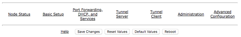
There are several control buttons below the configuration links section.
- Help
Opens a new window or tab to display the node help page.
- Save Changes
Click this button to save any configuration changes you have made. Saving changes will first do a basic validation of the new settings, saving them to flash memory if no errors are found. The new settings take effect in about 20 seconds and a reboot may or may not be required.
- Reset Values
Click this button to reload the currently saved settings from flash memory, effectively undoing any changes that were made.
- Default Values
Click this button to reset your node’s basic settings to the default values. This action does not affect your existing node name.
- Reboot
Click this button to force your node to reboot.
Basic Setup
You have already configured many of the basic settings, but there are several additional features that will be explained below.
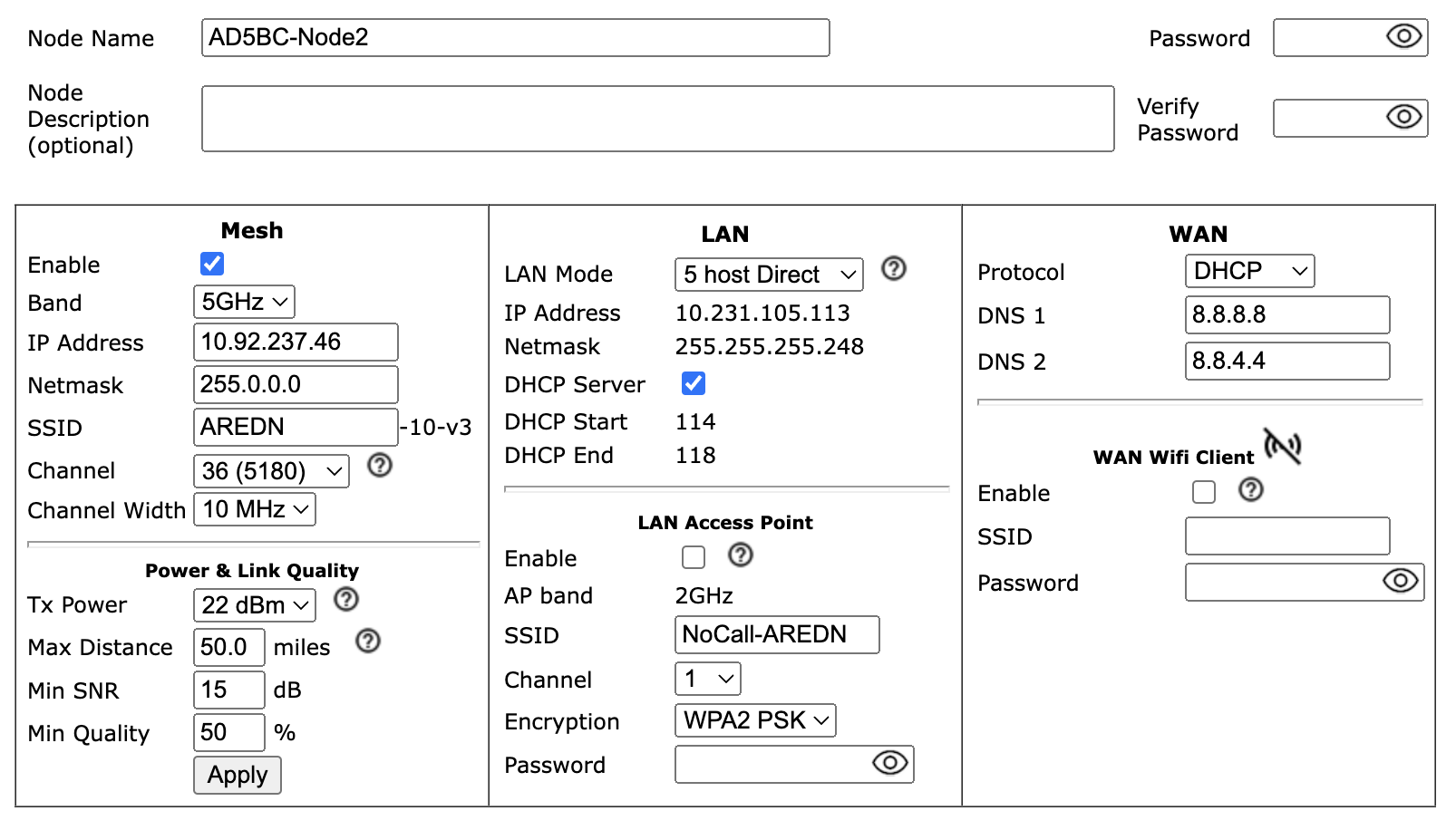
Mesh Column
Mesh is the node’s radio interface. The AREDN® firmware has been designed to simplify the process of configuring networking interfaces. Network values are automatically calculated based on the unique MAC addresses of your node. You may need to change the Channel and possibly the Channel Width parameters to match those of your local AREDN® mesh, as explained previously in the Basic Radio Setup section. Normally you will not need to change the other network settings on this page, so keep these values unless you fully understand how the mesh works and why the defaults may not be suitable for your situation.
- Channel Width Setting
Most AREDN® devices have a choice of using 20 MHz, 10 MHz, or 5 MHz channel widths. As a general rule, a larger channel width will allow more data to be transferred, but it may only do this over shorter distances. One suggestion is to start with the largest channel width that yields a Signal to Noise Ratio (SNR) of at least 15 dB.
Note
Some AREDN® devices will only support specific channel widths. If the choice of channel width is limited, the device will only show its supported widths in the Channel Width dropdown selector.
There may be several reasons why you might want to reduce the Channel Width setting:
To achieve a better SNR on a marginal link.
To extend the usable distance between neighbor nodes.
To increase the number of available channels in a crowded RF coverage area.
Please review the Network Design section for more information about designing a network that meets the specific requirements of your applications and services.
- Distance Setting
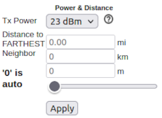
The Distance setting is only applicable to nodes that can communicate directly over RF. This setting adjusts the RF retry timer to define how long the transmitter will wait for an acknowledgement from a neighbor station. If the distance parameter is too short, the transmitter will send duplicate data packets before an acknowledgement has time to be received. If the distance parameter is too long, the transmitter will wait extra time before considering the data lost and retransmitting the packets.
Auto-Distance: A value of zero will cause the radio to automatically determine the RF retry timer by measuring the actual time it takes acknowledgement packets to be received. The timer is set using an Exponential Weighted Moving Average (EWMA). The auto-distance setting is best used on high quality, long distance point-to-point links between backbone or relay nodes. Fifty percent performance increases have been observed on those links compared to using a static distance setting.
Since auto-distance causes the node to calculate the best value based on actual data flow, it will require both time and adequate data traffic to arrive at the optimal setting. The node may not be able to arrive at the optimal values if a link is not being used to send a significant amount of data, because it starts at the max value and then drops down to the optimal setting. Over time the auto-distance setting should stabilize around the best value.
Attention
The auto-distance setting does not work well when nodes are in close proximity, when link quality is marginal, or when there are many nodes sharing the channel. In these cases the round-trip packet timing has a very wide range of values, so the timeout value becomes inflated and inconsistent. Static settings should be used in these situations.
A basic rule of thumb is when nodes are within five kilometers of each other you should test several static distance settings to see which one works best. The best way to test each distance setting is to use the iperf3 package between endpoint nodes to measure the throughput of the RF channel under different distance settings. See Test Network Links with iperf3 in the How-To Section for additional information.
- Configuring LQM Settings
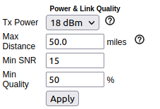
When Link Quality Manager is enabled, the Basic Setup page will show a slightly different group of settings for Power & Link Quality under the Mesh column.
- Max Distance
The maximum distance between nodes at which you can expect to achieve a usable radio link. The default value is 50 miles / 80 kilometers, but you can adjust this setting if your node is only able to maintain a usable radio link with closer nodes. Local conditions may dictate a shorter distance based, for example, on dense tree cover or other terrain features which impact line of sight communication. You can lower this value if you want to limit your node to linking only with nearby nodes.
- Min SNR
The minimum Signal-to-Noise ratio that you require in order to reliably pass data between nodes. The default is 15 dB, but you can adjust this value if you require your node to continue passing data even on links that have reduced signal characteristics.
- Min Quality
The minimum Link Quality required in order to reliably pass data between nodes. This is calculated as the moving average of total sent packets over total sent packets plus retransmissions. For example, if the node had to send every packet twice for it to be successfully received, the link quality would be 50%. An additional penalty is subtracted from Link Quality if the neighbor node is unpingable, and this is explained below under Ping Penalty in the Advanced Configuration section.
The Power & Distance settings can be adjusted and applied without saving changes or rebooting your node. However, they will return to their original values after a reboot unless you click Save Changes.
- Enable/Disable Mesh
You can disable your node’s radio interface by deselecting the Enable checkbox, saving your changes, and rebooting the node. With the Mesh interface disabled the Power & Distance settings no longer apply and will be hidden. Since your node now has an unused RF interface, you will notice that a new section appears which allows you to use the node’s radio as an FCC Part 15 LAN Access Point. You can enable or disable the LAN AP using the Enable checkbox. See the details below for configuring the LAN Access Point.
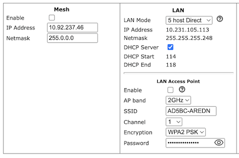
LAN Column
The LAN column contains the settings for the Local Area Network hosted by the AREDN® node. There are several options under the LAN Mode dropdown.
The default mode is 5 Host Direct. In this mode every host on the LAN has direct access to and from the mesh. This mode was created to reduce the amount of manual configuration needed to provide services to the mesh, since many services do not work well if they are hosted behind a NAT router. With Direct mode the LAN shares the same address space as the mesh at large. Port forwarding is not needed because NAT is not used, and there is no firewall between the LAN and the mesh.
The mesh address space is automatically managed, so you cannot configure the LAN network settings in Direct mode. The only configurable option available in Direct mode is the size of the LAN subnet which can accommodate either 1, 5, 13, or 29 LAN hosts. A one host subnet can be used for either a single server or a separate network router using its own NAT which is capable of more advanced routing functions than those available on a mesh node.
It is important not to use a subnet larger than is necessary because the chance of an IP address conflict on the mesh increases with the size of the subnet. The LAN subnet parameters are automatically calculated and depend on the IP address of the Mesh interface. If a conflict does occur it can be fixed by changing the Mesh IP address.
The other LAN Mode is NAT, and in this mode the LAN is isolated from the mesh. All outgoing traffic has its source address modified to be the Mesh IP address of the node. This is the same way that most home routers use an Internet connection, and all services provided by computers on the LAN can only be accessed through port forwarding rules. A single DMZ server can be used to accept all incoming traffic that is not already handled by other rules or by the node itself.
By default each node runs a DHCP server for its LAN interface, which lets the node assign IP addresses automatically for devices connected to the node’s local area network. The last octet of the start/end range for host IP addresses is shown in the LAN column. If you choose to disable the DHCP server, you must manually configure the host IP addresses to be within the LAN network range. There should be only one DHCP server for each IP address scope or range, so you may need to disable your node’s DHCP server if there is already another device providing DHCP services on your node’s local area network. Click this link for additional information on Dynamic Host Control Protocol.
When you connect a device to your node’s LAN, not only should it have an IP address in the LAN IP address range, but it is best practice for LAN devices to obtain their DNS Server information automatically from the node. Be aware that if a LAN device does not use the DNS Server entry provided by the node to which it is connected, then that device will be unable to resolve hostnames on the mesh network. Also, hard-coding a device’s DNS Server entry with the mesh node’s IP address could result in unexpected failures if that device is moved to another mesh node or network.
If you enabled the LAN Access Point feature mentioned previously, edit the access point’s SSID, channel, encryption method, and password. Select an AP channel that is within the range supported by your WiFi client devices. Click Save Changes to write your information to the node’s configuration, and a node reboot will also be required. Now wireless devices can connect to your node’s LAN wirelessly, and their DHCP IP address will be assigned by the node’s LAN DHCP server. If your node hardware has more than one unused radio, for example the Mikrotik hAP ac family with both 2.4 and 5.8 GHz radios in a single unit, the LAN Access Point section will always be visible whether or not your Mesh interface is enabled.
WAN Column
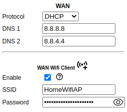
The WAN interface on your node is typically used to connect it to the Internet or to another external network. By default the WAN interface is set to obtain an IP address via DHCP from your upstream network. The DNS servers are set by default to use Google’s DNS services and should not be changed under normal circumstances. Google’s name resolution servers are configured properly to detect error conditions and report them correctly.
If you are not going to use the WAN interface on your node, you can select disabled from the Protocol dropdown list. If you will be using your node as a Tunnel Server, you should reserve an IP address on your router for the node’s WAN interface. This will be explained in the Tunnel Server section below. When a node has Internet access on its WAN interface, that access is available to the node itself and to any computers connected via the LAN port by default.
Note
The Advanced WAN Access settings have been moved to the Advanced Configuration display.
- WAN WiFi Client
As mentioned above in the Mesh section, if your node has a radio on which you have disabled Mesh and you are not using it as a LAN AP, you can enable this available radio as a WAN interface by checking the WAN Wifi Client checkbox. Enter the SSID and authentication string for the wifi AP that you want to connect through for Internet access.
The mesh node uses “WPA2 PSK” encryption to connect to the wifi AP. The password length must be between zero and 64 characters. If the key length is 64, it is treated as hex encoded. If the length is 0, then no encryption will be used to connect to an open AP. A single quote character must not be used in the passphrase.
To the right of the WAN WiFi Client label is an icon with hover text indicating the status of the WAN WiFi connection.
 indicates no wifi connection to the local access point.
  indicates a wifi connection but no Internet connection.
  indicates both a wifi connection to the local access point and a connection to the Internet.
After you Save Changes and reboot, the node will have Internet access via wifi rather than requiring a cable plugged into the node’s WAN port. In fact, enabling the WAN Wifi Client will disable VLAN1, so Internet access will no longer be possible through the physical WAN port. Also, on the Node Status display you will see the WiFi WAN Address label and IP address to indicate that your WAN connection is using the WAN WiFi Client.
Node VLANs
Many of the devices used as AREDN® nodes have only one Ethernet port, but more than one type of network traffic must share that single port. The AREDN® firmware implements VLANs in order to accomplish this. Different types of traffic are tagged to identify the network to which they belong.
- VLAN 1
Packets received by the node that are tagged for VLAN 1 will be identified as WAN traffic from the Internet or another external network.
- VLAN 2
Packets received by the node that are tagged for VLAN 2 will be identified as traffic from a DtD node directly connected via Ethernet cable.
- No VLAN tag
Packets received by the node that are untagged will be identified as LAN traffic from computers on the local area network.
It is important to understand AREDN® VLANs when configuring network smart switches for Internet access, tunneling, or DtD linking of nodes. There are some useful tutorials available on the AREDN® website for configuring VLAN-capable switches: Video or Text+Images. Also, on the AREDN® GitHub site there is more information about node VLANs that have been preconfigured in the firmware images for specific types of radio hardware. For additional information visit this link: Ethernet Port Usage
Port Forwarding, DHCP, Services, and DNS Aliases
Click the Port Forwarding, DHCP, and Services link to navigate to these settings. This provides a way for you to configure LAN network address reservations and service advertisements on your node. The page works differently based on the LAN Mode (Direct or NAT) that you are using on your node.
Direct Mode Operation
In Direct mode the LAN hosts are directly accessible from the mesh since no address translation or port forwarding is involved.
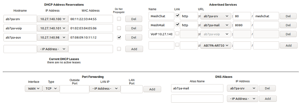
- DHCP Address Reservations
If your node has its DHCP server enabled, it will automatically provide IP addresses to connected hosts. Look under the Current DHCP Leases heading to see the existing hosts and their assigned IP addresses.
Attention
The hostnames of every device connected to the mesh at large must be unique. It is best practice to prefix your Amateur Radio callsign to the hostname of each of your devices in order to have the best chance of it being unique on the mesh network.
Since DHCP leases are dynamic and can change over time, there may be a reason why a host’s assigned IP address should be made permanent. This is especially useful if that host will provide an application, program, or service through your node to the mesh network at large. You can permanently reserve that host’s DHCP address by clicking the Add button at the right of the row in the Current DHCP Leases list. You will see that host now appears in the list under the DHCP Address Reservations heading above the list of leases.
There may be some devices on which you are not able to set the hostname prefixed by your callsign. Once you add that device to your DHCP Address Reservations, however, click the Hostname box to edit the hostname what will be propagated across the mesh network by your node. You may also want to assign a specific IP Address to the device by selecting it from the drop-down list. If you have a device which needs to be reachable on its host node, but which should not be accessed across the mesh network, click the Do Not Propagate checkbox to prevent OLSR from propagating that information to the mesh.
Once you have entered the values for your DHCP Reservation, click Add to add it to the list. You may also remove an existing reservation by clicking the Del button to delete it from the list. Click the Save Changes button to write your changes to the node’s configuration.
- Advertised Services
Advertised Services include the applications, programs, or functions that are available to devices on the mesh network. The purpose of the network is to transport data for the services which are being used. Network services may include keyboard-to-keyboard chat or email programs, document sharing applications, Voice over IP phone or video conferencing services, streaming video from surveillance cameras, and a variety of other network-enabled features.
Services can run on the node itself or on any of its LAN-connected devices. Remember that AREDN® nodes have limited system resources with which to run services, so installing add-on services directly on the node should be avoided because the node could become unstable if sufficient resources are not available for normal operation, particularly on devices with only 32 MB of memory. It is best practice to run services on an external computer connected to the node’s LAN network. In the example above you can see that an external host has been given a reserved DHCP address, and it is also running the MeshChat program as a service that is advertised on the network through this node. Use the following steps to create an Advertised Service.
- Name
Enter a service name in the Name field.
- Link
Check this box if your want your advertised service to display an active link in the web browser. This allows mesh users to navigate to your service by clicking the link in their web browser.
- Protocol
Enter the protocol to use in the field between Link and URL. Common protocols include
httpfor website services andftpfor file transfer services. Other services may use other protocols.- URL
From the dropdown list select the node or host on which this service is running. If you defined DNS Aliases as described below, you can also select a host alias from the dropdown list.
- Port
Enter the network port on which the host is listening for service connections. There may be several applications provided through a single web server on a node or host using a single port, and in that case a valid application Path must be entered after the port number (as in the example above). In other cases the network port alone uniquely identifies the application or program that is listening for user connections to that service. You can find additional information at the following link: Network Ports.
Once you have entered the values for your advertised service, click Add to add the service to the Advertised Services list. You may also remove an existing advertised service by clicking the Del button to delete it from the list. Click the Save Changes button to write your changes to the node’s configuration. A reboot is not required, and your new settings should take effect within thirty seconds.
- Service Advertisement Process
OLSR (Optimized Link State Routing) propagates service entries to other nodes across the network. Once every hour your node will verify that its own service entries are valid. Your node will not propagate services across the network if it finds any of these conditions:
The host is not pingable across the network
There is no service listening on the specified port
The HTTP link does not return a success status code
The package for this service is not yet installed
The node’s Advertised Services list will still show the defined service (with an alert icon and hover text marking it as non-advertised), but your node will not actually advertise that service to the network. If the service URL becomes reachable in the future or if the dependent package is later installed, then your node will resume advertising the service across the network.
- Port Forwarding
In Direct mode you will only be allowed to select the WAN interface so Port Forwarding is only meaningful for WAN-connected nodes. Enter the Outside Port being passed to your node from its upstream gateway, select a LAN host to process the requests, and enter the LAN Port on that host which is listening for those requests. Finally, click Add to add the port forwarding rule. You may also remove an existing rule by clicking the Del button to delete it from the list. Click the Save Changes button to write your port forwarding changes to the node’s configuration. More information can be found at this link for Port Forwarding.
- DNS Aliases
DNS Aliases provide a way for you to create a hostname alias for a services computer. This can be useful if you want a computer or device on your node’s LAN network to be identified by something other than its actual hostname. Your DNS Alias will be propagated across the network even if the actual hostname has Do Not Propagate checked in its DHCP Reservation, allowing you to hide the actual hostname while still advertising the alias on the mesh.
To create an alias, enter an Alias Name. The alias should be prefixed with your callsign in order to follow the naming convention used when defining any unique host on the network. Then use the dropdown selector to choose the name or IP Address of the existing host for which you are defining the alias. Once you have entered these values, click Add to add the alias to the list. You may also remove an existing alias by clicking the Del button to delete it from the list. Click the Save Changes button to write your changes to the node’s configuration.
Once an alias is defined, the DNS Aliases become available for creating Advertised Services. This feature can be used for virtual domain email servers, virtual machine identifiers, virtual web site URLs, and many other services.
Advanced DHCP Options
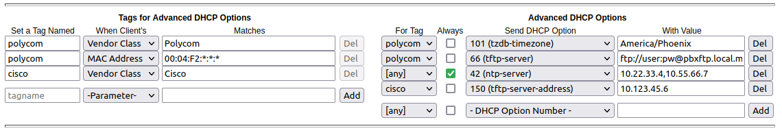
The Advanced DHCP Options section allows you to specify option codes and values which are sent to devices on your node’s LAN network at boot time. This provides an easy way to configure network clients during their boot process. In addition to providing an IP address, the DHCP protocol is able to send a large number of options for device configuration. Any LAN client device joining the network can request specific DHCP options in addition to its IP address. These Advanced DHCP Options are especially helpful for configuring and provisioning VoIP phones on your node’s LAN.
The Internet Assigned Numbers Authority (IANA) is the source for information about all DHCP options. Specific vendor equipment may or may not support all of the options, so you can verify which options are supported by referring to the manufacturer’s documentation for your LAN device.
- Tags for Advanced DHCP Options
The Tags for Advanced DHCP Options table allows the administrator to define DHCP tags that will be assigned to clients which are identified by specific values or properties such as Vendor Class or MAC address.
- Advanced DHCP Options
The Advanced DHCP Options table allows the administrator to specify DHCP options that will be sent to any client, or only to clients matching a specific tag. Option numbers can be entered directly or chosen from a list of well-known options. Option values are manually entered in the “with Value” field on each row.
Field data validation is implemented for any input field with easily recognizable content such as host name, MAC address, port and option numbers. Placeholders are also supplied for input fields that might otherwise be difficult to describe (such as MAC addresses) using wildcard matching. Once the appropriate values are entered, click the Add button to include the settings which were defined. You may also delete a row by clicking the Del button for that row. After you have added, changed, or deleted your Advanced DHCP Options, click the Save Changes button at the top of the page.
NAT Mode Operation
If you are using NAT for your LAN mode, then hosts on the LAN are isolated from both the Wifi and WAN interfaces by a firewall. This makes them inaccessible from either of these interfaces unless Port Forwarding is configured. In this mode all outgoing LAN traffic has its source address modified to be the Mesh IP address of the node. This is the same way that most home routers use an ISP Internet connection.
- Port Forwarding
Port forwarding rules can redirect inbound connections from the Wifi, WAN, or both interfaces and forward them to an IP address and port on the LAN. The destination port need not be the same unless you are forwarding a range of ports as explained below.
To create a port forwarding rule, select the network Interface on which the traffic will enter your node. Select the Protocol Type used by the incoming packets (TCP, UDP, or Both). Enter the Outside Port number that the external request is using to connect to your service. When your node receives traffic on the selected interface, protocol, and port then that request will be routed to the LAN IP address and LAN Port of the host which is listening for incoming requests for that service.
Once you have entered these values, click Add to add the rule to the Port Forwarding list. You may also remove an existing rule by clicking the Del button to delete it from the list. Click the Save Changes button to write your port forwarding changes to the node’s configuration.
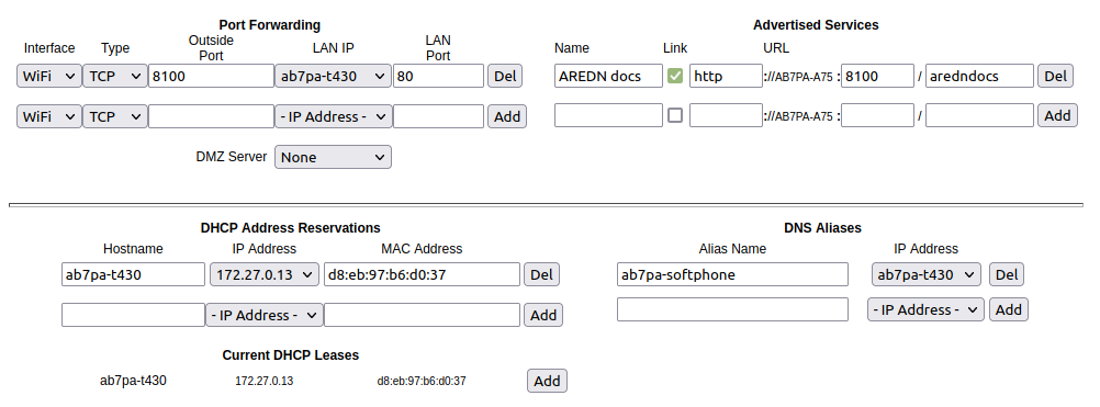
- Example:
On the LAN of a mesh node called
ad5oo-mobilethere is an IP camera with an IP address of 172.27.0.240 which is running its own web display. To make that camera available to everyone on the mesh, create a port forwarding rule on the WiFi interface whose Outside Port is any unused port on your node (for example8100) with an LAN IP of 172.27.0.240 and LAN Port of80. This takes all connections to port8100onad5oo-mobileand redirects them to port80on 172.27.0.240. In a web browser on a remote computer connected to the mesh you could go tohttp://ad5oo-mobile:8100to view the IP camera.
If you want to forward a range of ports, the Outside Port field will accept a hyphen-separated range in the form “xxxx-xxxx”. When doing this, set the LAN Port to the low value of the port range.
If you want to forward every port that is not already in use to a single computer on the LAN, choose that host’s IP Address from the DMZ Server dropdown. There can be only one DMZ Server. Be aware that this bypasses the firewall in the node, so the DMZ server should run its own firewall to prevent unauthorized access.
Note that port forwarding to an FTP server, which uses both ports 20 and 21, can be done with a single rule using port 21 if the ftp client is capable of using passive ftp mode. Web browsers are able to do this and handle ftp downloads seamlessly.
- Advertised Services
In
NATmode Advertised Services will not be accessible until at least one port forwarding rule or a DMZ server has been defined as described above. Advertised Services are entered as they are for Direct mode, except that the URL field is always that of your node which is handling network address translation. The port number should be the one used as the Outside Port in the forwarding rule through which the service will be accessed. In the last field you can enter an optional path if needed, such as the name of a specific folder on a web server or a directory on an ftp server.Click Add to add the service to the Advertised Services list. You may also remove an existing service by clicking the Del button. Click the Save Changes button to write your changes to the node’s configuration.
- DHCP Address Reservations
DHCP Address Reservations make a LAN device’s IP address permanent so it can be used consistently when defining Port Forwarding rules, and they are added the same way as in Direct mode. If a LAN device is currently connected and has been given an IP address by DHCP then it will appear under Current DHCP Leases. If you click the Add button next to the lease then it will be added to the DHCP Reservations list. You may also remove an existing reservation by clicking the Del button to delete it from the list. Click the Save Changes button to write your changes to the node’s configuration. When using
NATmode the IP addresses of LAN devices are never propagated across the mesh, so the Do Not Propagate checkbox will not appear on this page.- DNS Aliases
DNS Aliases work differently in
NATmode. Aliases cannot be propagated across the mesh, and they cannot be used when defining an Advertised Service. They can only be used as an alternate name for a device on the nodes’ LAN.
Tunnel Links
Tunnels are typically used as a means of connecting mesh islands if RF links cannot be established. Before using the AREDN® tunnel feature, be aware of how this type of connection could impact your local mesh network. If your node participates in a local mesh, then adding one or more tunnel connections on that node will cause the nodes and hosts on the far side of the tunnel(s) to appear on your local Mesh Status display. This adds complexity and makes everyone’s display a little more difficult to navigate. If you want to participate in remote mesh networks via tunnel, consider establishing those tunnels from one of your nodes that is not connected to your local mesh network. Also, remember that AREDN® is first and foremost an emergency communication resource, so it’s possible that Internet-dependent links and the assets they provide will not be available during a disaster.
Internet Connectivity Requirements
In order to run your node as either a Tunnel Server or Tunnel Client, you will need to configure Internet access. The following diagram shows an example of tunnel services between two nodes using the Legacy Tunneling Protocol described below.
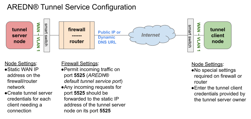
If you are using Mikrotik hAP ac family devices or GL.iNET devices then these nodes have built-in switches with the appropriate VLANs preconfigured in the AREDN® firmware. If you are using any other type of node, then you will need to configure a separate VLAN-capable switch. Set your VLAN-capable network switch to appropriately tag traffic from the Internet with “VLAN 1” before sending it to your node. This allows your node to properly identify the traffic as coming from the Internet connection on its WAN interface. See the equipment manual for your smart switch to determine how to configure these settings.
Tunnel Server
Click the Tunnel Server link to navigate to these settings. This section provides a way for you to configure node-to-node connections across the Internet. The heading area displays information for both types of tunneling protocols. The legacy tunneling service provides an unencrypted connection between the linked nodes, while the Wireguard tunneling service provides an encrypted connection over the Internet. Tunnel network address ranges are calculated automatically and it is not necessary to change these settings unless there is a specific reason why the defaults will not work for your situation. The Tunnel Server DNS Name is the public IP Address or the Dynamic DNS name by which Internet-connected nodes can reach your network.
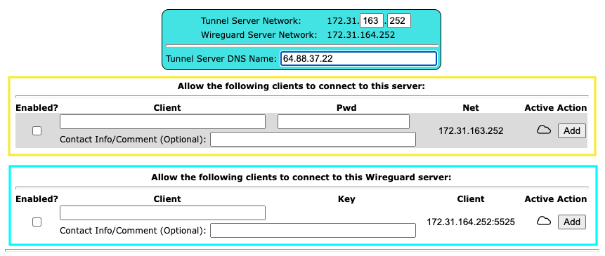
- Legacy Tunneling Protocol
The top section is for entering tunnel clients for the AREDN® legacy tunneling protocol which uses TCP and is unencrypted. In the Client field enter the exact node name of the client node that will be allowed to connect to your tunnel server. Do not include the “local.mesh” suffix. In the Client Password field enter a password that the client node will use to connect to your node over the tunnel. Use only uppercase and lowercase characters and numbers in your password. You may also enter other optional information in the Contact Info/Comment field. To allow the client to connect to your tunnel server, select the Enabled checkbox.
Once these settings are correct, click Add to add the new client to the list of authorized tunnel clients. On the right of each entry there is an envelope icon which will automatically open your computer’s email program and copy the client settings into a new email which allows you to quickly and easily send credentials to the owners of the client nodes.
In order for your Internet-connected router/firewall to have a consistent way to forward traffic to your node, it is best practice to set a static IP address on your tunnel server node’s WAN interface or to reserve its DHCP IP address in your router.
On your Internet-connected router/firewall set the firewall rules to permit TCP traffic from the Internet on port
5525. Then configure a port forwarding rule to send any traffic from the Internet on port5525to the IP address of your node’s WAN interface.- Wireguard Tunneling Protocol
The bottom section of the Tunnel Server page is for entering tunnel clients that will use the Wireguard tunneling protocol which uses UDP and is encrypted over the Internet. In the Client field enter the exact node name of the client node that will be allowed to connect to your tunnel server. Do not include the “local.mesh” suffix. You may also enter other optional information in the Contact Info/Comment field. To allow the client to connect to your tunnel server, select the Enabled checkbox.
Once these settings are correct, click Add to add the new client to the list of authorized tunnel clients. The entry for the Key field will be auto-generated when the Add button is pressed. You will also see the port which was assigned to the entry in the Client field at the end of the IP address. On the right of each entry there is an envelope icon which will automatically open your computer’s email program and copy the client settings into a new email which allows you to quickly and easily send credentials to the owners of the client nodes.
Note
If you change the Client Name on one of your existing Wireguard clients, the existing security key will be automatically retired and a new key will be generated. This may occur if the client node owner has changed its name, or if the Tunnel Server administrator needs to reuse/repurpose an existing line on the Tunnel Server display.
In order for your Internet-connected router/firewall to have a consistent way to forward traffic to your node, it is best practice to set a static IP address on your tunnel server node’s WAN interface or to reserve its DHCP IP address in your router.
On your Internet-connected router/firewall set the firewall rules to permit UDP traffic from the Internet on an appropriate range of ports. The starting port should be
5525, which will provide for one wireguard tunnel connection. If you want to allow up to 10 wireguard tunnel links (for example), you would permit UDP traffic on the range of ports between5525-5534. Then configure a port forwarding rule to send any traffic from the Internet on your range of ports to the IP address of your node’s WAN interface.- Supernode Tunneling
Supernode tunneling uses the Wireguard tunneling protocol, but the port range begins with port
6526. On your Internet-connected router/firewall set the firewall rules to permit UDP traffic from the Internet on an appropriate range of ports. The starting port should be6526, which will provide for one supernode tunnel connection. If you want to allow up to 10 supernode tunnel links (for example), then you would permit UDP traffic on the range of ports between6526-6535. Then configure a port forwarding rule to send any traffic from the Internet on your range of ports to the IP address of your node’s WAN interface.
Once the client information has been entered, click the Save Changes button. When a tunnel connection becomes active, the cloud icon at the right of each row will change to indicate that the tunnel is active. Depending on the timing of the webpage refresh, you may need to press the Refresh button to see the active icon.
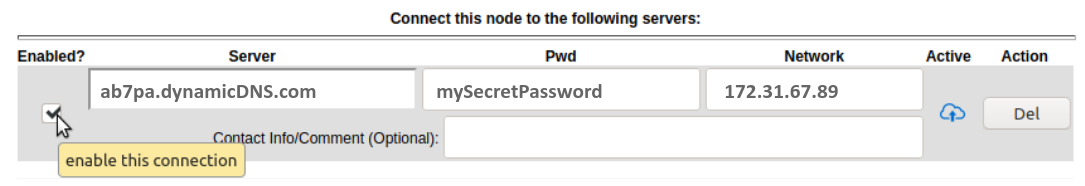
Tunnel Client
Click the Tunnel Client link to navigate to these settings. In this section you can configure your node to connect over the Internet to another node running as a Tunnel Server. You should already have your VLAN-capable network switch configured as explained in the Internet Connectivity Requirements section above, if it is needed.
Contact the amateur operator who controls the tunnel server and request client credentials by providing your specific node name. The tunnel server administrator will provide you with the public IP or DDNS name for the tunnel server, the password/key you are to use, and the network IP address for your client node. Enter these values into the appropriate fields on your node and click Add to create a client entry in the list.
If your tunnel server administrator used the envelope icon to create an email to send you the credentials, you can simply highlight/select the credentials from the email, copy the selection, and then paste that selection into any of the blank fields for a new Tunnel Client row. Your node will correctly populate each of the separate fields with the credentials you were sent.
To allow your client to connect to the tunnel server, select the Enabled checkbox and click the Save Changes button. When a tunnel connection becomes active, the cloud icon at the right of each row will change to indicate that the tunnel is active. Depending on the timing of the webpage refresh, you may need to press the Refresh button to see the active icon.
Administration
Click the Administration link to navigate to these settings. There are four sections that provide ways for you to manage the firmware, packages, security keys, and support data on your node.
- Firmware Update
There are currently three ways to update the firmware on your node. No matter which method you choose, you can retain your existing configuration settings by selecting the Keep Settings checkbox.
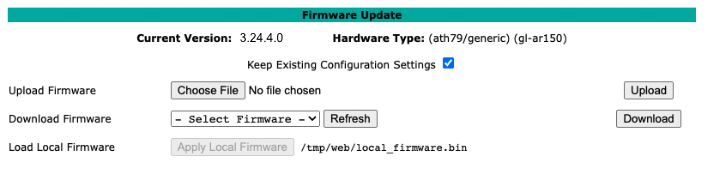
Upload Firmware: If you have a new firmware image that you have already downloaded to your computer from the AREDN® website, click the Browse button and select the firmware file from the location on your computer where you saved it. Click Upload and the file will be uploaded and installed on the node.
Download Firmware: If your node has Internet access you can use the Download Firmware option. Click Refresh to update the list of available images. The source URLs that are queried are those listed on the Advanced Configuration page of your node. Select the image to download, click Download, and wait for the firmware to download and be installed.
Load Local Firmware: If you need to upgrade the firmware on a node which has a marginal connection to the network, the standard web/http method may not reliably transfer the image to the node. In this situation you may want to use an independent means of uploading the firmware to the node before beginning the upgrade process. Choose an upload method such as
scp(secure copy) with a long connection timeout, which may allow the file transfer to continue the upload in the event of a network interruption. Transfer the new firmware file to your node, place it in the/tmp/webfolder, and name itlocal_firmware.bin. Refresh your node’s Administration page and once the page detects the/tmp/web/local_firmware.binfile, then the Apply Local Firmware button will become active. Press this button to begin the update process using the firmware you previously uploaded.
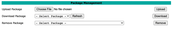
- Package Management
Here you can install or remove software packages on the node. Upload Package allows you to install a package file by uploading it from your computer to your node. Download Package allows Internet-connected nodes to retrieve a package from the AREDN® website. Clicking Refresh will update the list of packages available for download.
The Remove Package list shows all packages currently installed on the node. Selecting a package and clicking Remove will uninstall the package. You will only be able to remove packages that you have added. All installed packages are shown, but the pre-installed packages cannot be deleted since they are necessary for proper operation of the node.
As of NB 20230916, when you install extra packages, your node will remember them in its package store. When you next upgrade your node’s firmware, the package store will be retained. After the firmware upgrade your node will wait for a few minutes and then automatically install the extra packages in its package store. If you uploaded the package to the node, then the package store keeps a copy of the package code itself. If you downloaded the package, then your node will attempt to redownload it. Also, if you later remove one of your extra packages, it will be automatically removed from the package store.
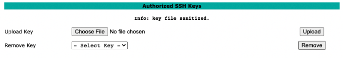
- Authorized SSH Keys
Uploading ssh keys allows computers to connect to a node via ssh without having to know the password. The ssh keys are generated on your computer using built-in utilities or the PuTTY program’s Key Generator. Once you have the key files on your computer, you can upload its public key to your AREDN® node. If you want to remove an installed key, select it and click the Remove button.
Note
If you plan to use ssh keys you may want to review Use PuTTYGen to Make SSH Keys in the How-To Guide section which describes this process in detail for users of Microsoft Windows computers.
- Support Data
There may be times when you want to view more detailed information about the configuration and operation of your node, or even forward this information to the AREDN® team in order to get help with a problem. Click the Download Support Data button to save a compressed archive file to your local computer.
Advanced Network
If you have a supported multiport device (currently Mikrotik ac2, or ac3 only), then you will see a menu option for Advanced Network. This provides a way for you to configure the ports on your multiport node. For more information on the AREDN® VLANs being used, refer to the Node VLANs description in the Basic Setup section above.
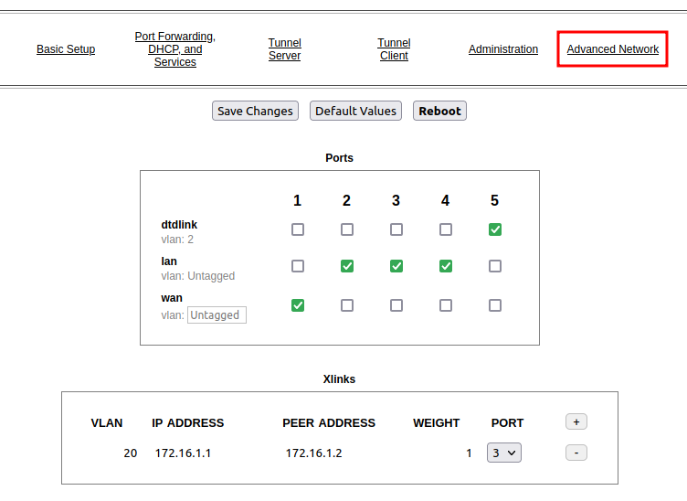
- Ports
The Ports section shows the available ports across the top and the possible configurations along the left side. The default configuration is as follows:
The first port is configured as a WAN port. The data entry field to the right of the vlan label can contain any valid vlan identifier if it is required, typically in the range between 1 and 4094. The default for these multiport devices is no vlan (untagged), so leave the default unless there is a specific reason why it is required in your situation.
The middle ports are configured as LAN ports with no vlan (untagged).
The last port is configured for DtD linking to another AREDN® node with vlan2 (tagged).
You should only have one box checked for each port. If you want to change a port’s configuration, simply uncheck the existing box and check the box for the new setting on that port.
- Xlinks
A cross-link allows your node to pass AREDN® traffic across non-AREDN® point-to-point RF links. To add a cross-link click the plus icon, enter an unused VLAN number for the link, the IP address of the near-side radio, the IP address of the far-side radio, a weighting factor, and the port to which the near-side radio is connected on your node. The Weight will be used by OLSR to determine the best route for AREDN® traffic. If you want to remove a cross-link, simply click the minus icon on the right side of the row to remove.
When you have finished making configuration changes to the ports and cross-links, click the Save Changes button. You will be notified if a reboot is required to activate your changes, and you can then click the Reboot button.
Advanced Configuration
The Advanced Configuration section allows you to change settings for various items that may be available on the type of hardware you are using. Not all hardware can support every value. These settings are best left as default unless you have a clear understanding of why you need to change the defaults for your node or network.
Above the settings table there are links that allow you to view the node help file, reboot the node, or reset the node to a firstboot or “NOCALL” configuration. You can edit or select a setting and then click the Save Setting button at the right side of the row to implement the change. You may also reset an item to default values by clicking the Set to Default button. For some settings you may need to reboot your node to apply the change, and in that case a message will be displayed notifying you that a reboot is required.
Link Quality Manager (LQM) Settings
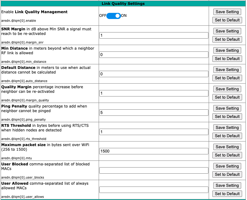
The basic LQM settings were described above under the Mesh Column, but additional LQM settings are also available here in the Advanced Configuration section.
- Enable
Enable or disable the LQM feature in its entirety.
- SNR Margin
The margin above the Minimum SNR that must be detected in order for a node to be returned to the active list based on signal level. The default value is 1 dB.
- Minimum Distance
The minimum distance (in meters) that must exist between nodes in order for a link to be considered for activation. The default value is 0 meters. This value can be increased if you do not want your node to pass traffic with nearby nodes, for example at a tower site with collocated backbone nodes designed to link only with other distant nodes.
- Default Distance
The distance (in meters) to use when the actual distance between nodes cannot be calculated from their GPS coordinates. The default value is zero, which causes the node to treat nodes as being collocated.
- Quality Margin
The margin above the Minimum Quality that must be detected in order for a node to be returned to the active list based on quality. The default value is 1 percent.
- Ping Penalty
The Link Quality penalty that is imposed on calculations if a remote node does not respond to a ping request. The default value is 5 percent. This setting may be helpful for cases when a link would otherwise be marked active but the remote node is currently unreachable on the network.
- RTS Threshold
The packet size in bytes triggering RTS/CTS when LQM detects hidden nodes. The default value is 1.
- Maximum Packet Size
The maximum size of a packet which is sent over WiFi. The value is between 256 and 1500 with a default of 1500 bytes. Decreasing this value can improve link quality in some cases, especially in noisy environments with long distance connections.
- User Blocked Nodes
A comma-separated list of MAC addresses which you desire to block from your neighbors list. This feature allows you to “blacklist” specific nodes. RF nodes are blocked by their Wifi MAC address, while DtD nodes are blocked by their LAN MAC address. MAC addresses are typically entered as uppercase characters with the hex pairs separated by colons.
- User Allowed Nodes
A comma-separated list of MAC addresses which you always want to allow. This feature allows you to “whitelist” specific nodes. RF nodes are allowed by their Wifi MAC address, while DtD nodes are allowed by their LAN MAC address. MAC addresses are typically entered as uppercase characters with the hex pairs separated by colons.
WAN Settings
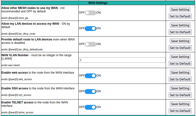
Several WAN access settings can be adjusted in this section. It is recommended that these settings be left at their default values, but specific use cases may require you to change them.
- Allow MESH nodes to use my WAN
The default value is
OFFand it is recommended that you use this default unless there is a special reason to enable it. Setting the value toONwill allow this node to route traffic from its Mesh interface to/from your WAN interface. Since the WAN interface typically provides a gateway to the Internet, it is not desirable to route Internet traffic over your Mesh interface. AREDN® is an FCC Part 97 amateur radio network, so be sure that any traffic which will be sent over the radio complies with FCC Part 97 rules. If you want local devices to have wireless Internet access, consider using an FCC Part 15 access point instead of your node’s WAN gateway.In older firmware releases there was a checkbox on the Basic Setup display for this setting. In the past if you checked “Allow others to use my WAN” then here is what your slider would look like in the current firmware:
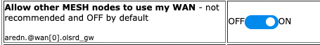
Remember that the default value is
OFFand you should not turn it on unless you have a special use case.- Allow my LAN devices to access my WAN
The default value is
ONwhich allows your LAN-connected devices to access your node’s WAN network. Setting this value toOFFwill prevent LAN devices from accessing the WAN, which means that your LAN hosts will not be able to reach the Internet even if your node has Internet access via its WAN. You may need to disable WAN access if your device needs to be connected to two networks at once, such as an Ethernet connection to your node as well as a WiFi connection to a local served agency network.In older firmware releases there was a checkbox on the Basic Setup display for this setting. In the past if you checked “Prevent LAN devices from accessing the WAN” then here is what your slider would look like in the current firmware:
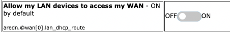
Remember that the default value is
ONand you should not turn it off unless you have a special reason to do so.- Provide my LAN devices with a default route
Your node’s DHCP server provides routes to LAN devices so they can access its available networks. A default route is required for WAN access, and that is provided automatically if “Allow my LAN devices to access my WAN” is
ONas discussed above. However, some LAN devices (such as certain IP cameras) may not support DHCP option 121 and will require a default route in order to access the mesh network. Setting this value toONwill provide a default route to those devices. If a LAN device is connected to two networks at once, such as an Ethernet connection to your node as well as a WiFi connection to a local served agency network, care should be taken to understand how the device will deal with default routes to more than one network.Remember that the default value is
OFFand you should not turn it on unless you have a special reason to do so.- WAN VLAN Number
Important
This feature only applies to node hardware which requires a VLAN tag for the WAN interface. It will not appear on hardware where the Ethernet ports are on a switch chip, since changing the default VLAN number is not supported on those devices at the present time. It will appear as a
blankfield on devices that have a dedicated WAN port and therefore do not need a VLAN tag for their WAN interface.If you have node hardware that uses a VLAN tag for the WAN interface, then the default WAN VLAN identifier is
1. In some cases this default VLAN may be in use already or may be reserved by other equipment on your network. This field allows you to change the VLAN number being used on your node’s WAN interface.Warning
If you plan to change this setting, do not use single digit identifiers or any number larger than can be supported by your network equipment. Different types of network equipment can support various numbers of VLANS, but the maximum number is limited by the 802.1Q standard to no more than 4094.
- Enable Web, SSH, or Telnet Access
HTTP, SSH, and Telnet access to your node is enabled by default on your node’s WAN interface. If you need to restrict this access to your node from the WAN, then you can turn it
OFFhere.
PoE and USB Power Passthrough
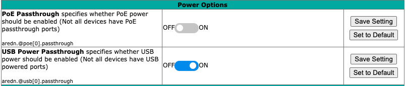
These rows will only appear in the table if you have node hardware which supports PoE or USB power passthrough. One example is the Mikrotik hAP ac lite which provides one USB-A power jack, as well as PoE power passthrough on Ethernet port 5. You are allowed to enable or disable power passthrough on nodes with ports that support this feature. Move the slider to ON and click Save Setting to enable power passthrough.
Tunnel Options
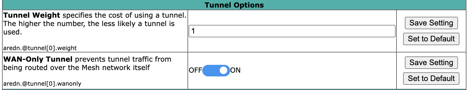
- Tunnel Weight
This specifies the OLSR route cost of using a tunnel, with the default value set to
1. The higher the route cost weight, the less likely a tunnel will be chosen for routing traffic.- Tunnel WAN Only Setting
This setting is enabled by default and it prevents tunnel traffic from being routed over the Mesh network. It limits tunnels to using the WAN interface, which is typically the intended route. If in your situation you need tunnel traffic to be routed over RF to a node with WAN access, then you can disable this setting to allow that traffic to pass.
Watchdog Settings
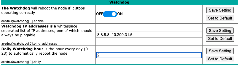
- Watchdog
Watchdog is a background monitor that keeps track of core node processes. If any of the processes is having issues, Watchdog will reboot the node. This feature is
OFFby default, but it can be enabled by moving the slide switch to theONposition and clicking the Save Setting button. Currently the set of node processes that are monitored include olsrd, dnsmasq, telnetd, dropbear, uhttpd, and vtund (if tunneling is enabled).- Watchdog IP Addresses
You may also include one or more IP addresses, one of which should always be pingable. Your node will be rebooted if none of the IP addresses are reachable across the network. Enter IP addresses as a whitespace-delimited list.
- Daily Watchdog Hour
Enter an integer between 0 - 23 which represents the hour of each day that you would like Watchdog to automatically reboot your node. The default is an empty field, in which case Watchdog will not auto-reboot your node.
Memory Settings
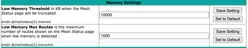
As the number of nodes increases in a mesh network, the processing requirements also increase for displaying all of the mesh routes on your node’s Mesh Status display. For older nodes with limited memory resources, the mesh status display may become very sluggish on large mesh networks.
Recent firmware improvements have made the Mesh Status display much more responsive, but two Advanced Configuration values have been included for setting the Low Memory Threshold and maximum number of routes to be displayed.
Currently the default low memory threshold is 10,000 KB, which if reached will limit the Mesh Status display to the 1,000 closest routes. These values can be adjusted to lower values if your node has limited memory.
Supernode Settings
Supernodes are a way to link multiple mesh island networks in a safe and efficient way. If your local node is part of a network with a Supernode then you have the ability to view other nodes which are part of the Cloud Mesh network. This feature is ON by default and results in a new button being displayed on your Mesh Status page. The Cloud Mesh button will navigate to the Mesh Status display of the closest Supernode available to your device. For further information see the Supernode Architecture description in the Network Topologies section of the Network Design Guide.
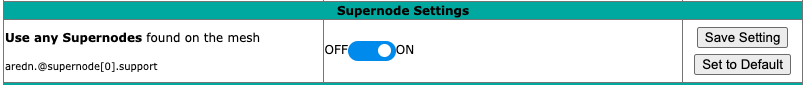
- Use any Supernodes
This switch enables or disables support for viewing remote networks connected through Supernodes. The default value is
ONwhich means that your node will check for Supernodes and allow you to navigate to other networks via the Cloud Mesh button. Switching this valueOFFwill remove the Cloud Mesh button from your Mesh Status display.
Network Tools
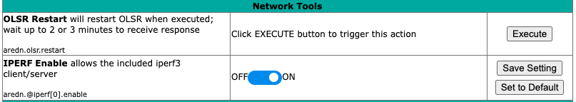
- OLSR Restart
The OLSR (Optimized Link State Routing) process can be restarted when you want your node to rebuild its mesh routing table but you do not want to do a full reboot. Click the Execute button to restart OLSR.
There is a known intermittent issue that may occur when a node boots. If OLSR fails to propagate information or does not receive all the network hostnames, a one-time restart of OLSR should resolve the issue. OLSR should be restarted on your node if other nodes’ Mesh Status display have your node’s IP address rather than hostname or if “dtdlink” or “mid” is shown in your node’s hostname on their Mesh Status display. If your node’s Mesh Status display shows the IP address rather than hostname for a remote node, then that remote node should restart OLSR.
- iperf CGI Feature
The iperf CGI feature is described in the “Test Network Links with iperf3” section of the How-To Guide. It is enabled by default, but if you do not want your node to participate in any remote iperf tests then you can disable its ability to respond to those queries using this setting. Move the slider to
OFFand click Save Setting.
Remote Logging URL
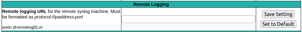
This field allows you to enter the URL for a remote syslog server. If this URL is provided, then your node will send log messages to the remote server using the specified IP address, port, and protocol.
Map Tile and Script Paths
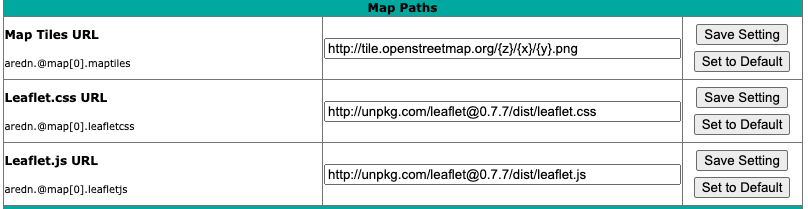
These fields contain the external URLs for map tiles and leafletjs css and javascript files used for interactive maps.
Firmware and Package Download Paths
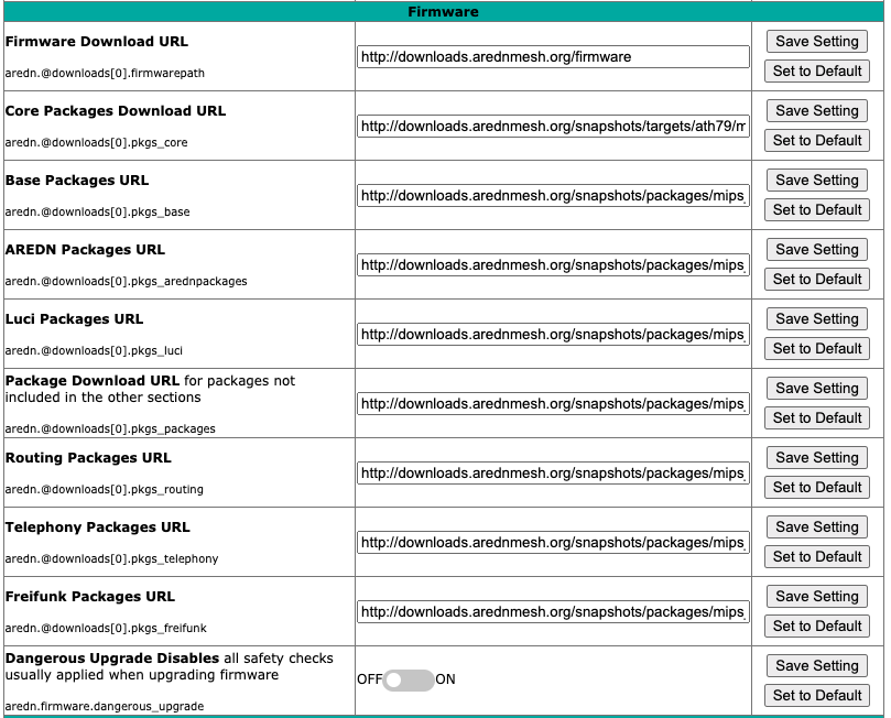
These fields contain the URLs used by the node for downloading firmware and package files during upgrades. By default they point to the AREDN® downloads server available across the Internet. You can change these paths to point to a local mesh package server in order to upgrade nodes that do not have Internet access. If you plan to create a local software repository for your mesh network, review Creating a Local Package Server in the How-To Guide section.
The Dangerous Upgrade setting allows you to disable the normal firmware compatibility safety checks that typically prevent you from loading the wrong firmware image on your node. The default setting is OFF which means that the safety checks remain enabled, and this setting should not be changed unless you have a specific reason to disable the firmware compatibility checks. One example for using this setting would be if you mistakenly installed an incorrect firmware image and would like to correct that mistake by installing the correct firmware image (e.g., you installed the Mikrotik LHG version when you meant to install the LHG XL version).
AREDN® Alert Messages
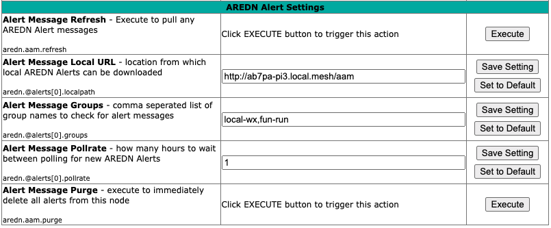
- Alert Message Refresh
The AREDN® development team may post messages which Internet-connected nodes can automatically download. You can execute the aam.refresh action if you want your node to retrieve any new messages without having to wait for the next auto-refresh window. Click the Execute button to trigger an immediate message retrieval. This will retrieve all alerts eligible for display on your node, whether they come from the AREDN® server over the Internet or from a local message source on your mesh network.
- Alert Message Local URL
This field allows you to enter the URL for a local alert message repository. If you configure such a local repository then your nodes without Internet access can also receive alert messages pertinent to your local mesh. Enter the URL without a trailing backslash.
A local message repository can be configured on a mesh-connected web server which allows nodes to query the URL you entered. No Internet access is required for this feature to work. You can consult with your local server administrator in order to obtain the correct URL for the local message repository. You can find more information about AREDN® Alert Messages in the Getting Started guide under the Node Status section.
There is also a separate package called AREDN Alert Message Manager which allows the local message repository to be hosted on a node itself, rather than requiring a separate LAN-conneted web server. You can find out more about this application by looking for AREDN Alert Message Manager in the Applications and Services Guide under the Other Services section.
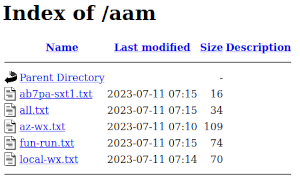
Use the following file naming convention on the web server:
Create text files for individual node messages by using only lowercase characters with the exact node name, followed by the
.txtextension as shown below. Whitespace characters are not allowed in node names.Create text files for group messages by using only lowercase characters with the group name, followed by the
.txtextension. Whitespace characters are not allowed in group names.To create a broadcast message intended for all local nodes, enter your message text in a file named
all.txtusing only lowercase characters for the filename.
It is possible to include HTML tags in your message text, such as using the
<br />tag to display subsequent text on the next line. However, it is best practice to keep alert messages short in order to minimize the height of the alert banner displayed on node webpages.- Alert Message Groups
In addition to local alert messages, it is possible to receive group alert messages. Group alert messages allow node operators to organize the mesh network into administrative/geographical domains or alert types using group labels. Multiple group names can be added to this field as a comma separated list.
Group alerts could be used by local operators to create a consistent alert structure. The following are some examples:
Geographic regions (State, county, ARRL section, neighborhood)
Connection types (backbone, leaf nodes, tunnels)
Infrastructure Change Management notices
Weather alerts
Wildfire, flooding, tsunami or volcano alerts
SKYWARN activations, DHS threat level
The group alert messages are retrieved from the web server specified in the local URL field. Alerts for a group are stored in a file named with the group name in all lowercase and a
.txtextension as described above.- Alert Message Pollrate
This field allows you to set the polling rate or interval in hours at which the node will check for message updates. The default polling rate is once every 12 hours, but you can make this value smaller if you want your node to check for updates more frequently.
- Alert Message Purge
Use this purge setting if you want to immediately remove the AREDN® Alert Message banner from your node. Click the Execute button to trigger an immediate message banner removal. This will remove all alert messages, whether they originated from the AREDN® server over the Internet or from a local message source on your mesh network.