Installing AREDN® Firmware#
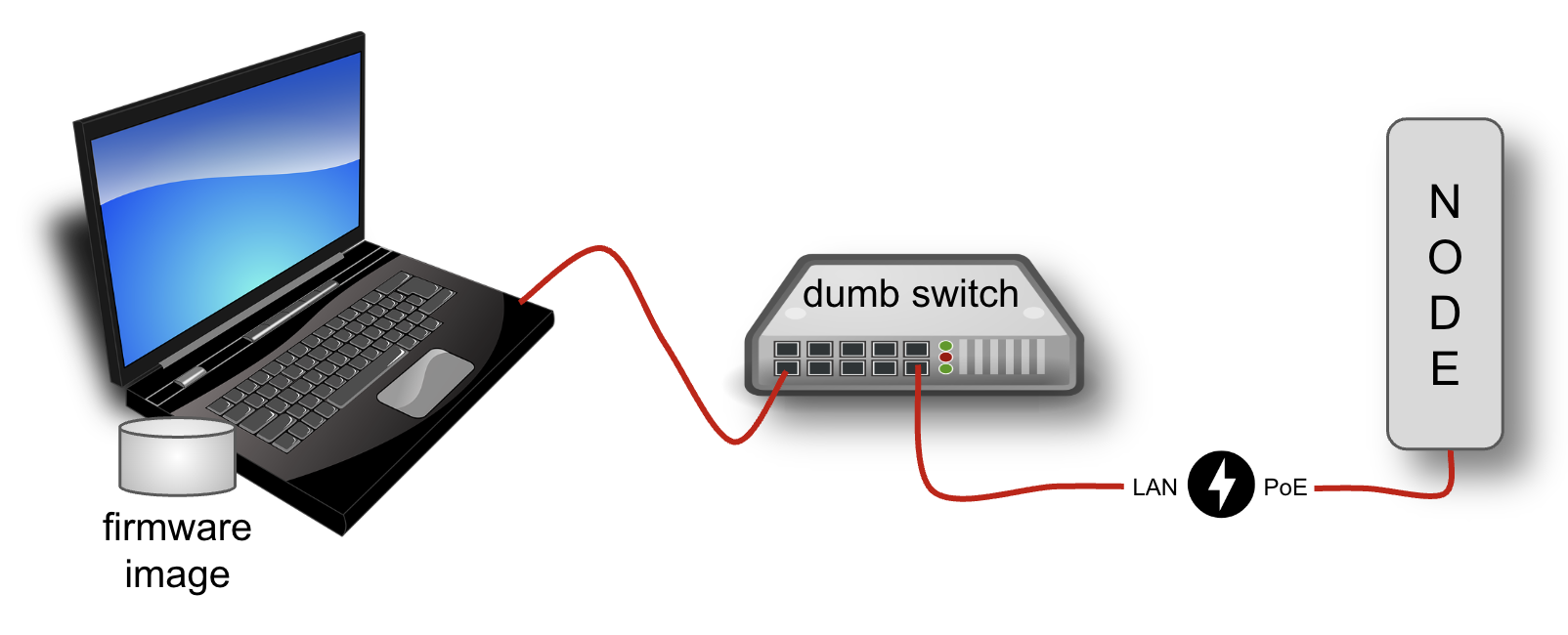
The diagram below shows your computer with the downloaded firmware image connected to the node using Ethernet cables in order to install the AREDN® image. It is highly recommended that you connect the computer and node through a simple (dumb) Ethernet switch so that the switch can maintain the computer’s network link even when the node is rebooting. Do not use a network router for this purpose – only a dumb switch. This is not for the sake of the radio, but it allows your computer to maintain its Ethernet interface link even when the node reboots.
In the Firmware Tips section of the How-To Guide you will find assistance if you experience an issue uploading firmware to your device. The How-To Guide also contains a Virtual Machine Installs section for help installing x86_64 firmware images on a VM for a virtualized node.
Preparing your computer#
- Setting a Static IP Address on your Computer
For all of the device models discussed below you will be asked to set a static IP address on your computer as part of the install process. Various computer operating systems have different ways of accomplishing this, so you should check your computer manuals, publications, and online resources to walk you through the steps for your specific computer.
As mentioned above, AREDN® recommends that you connect your computer to the node through an intermediate network switch. This allows your computer to activate its Ethernet interface with the static IP address even when the node is not powered on. Since node hardware needs to be powered on/off or rebooted during the install process, the network switch will keep your computer’s network interface active on its static IP address.
If you choose not to use an intermediate network switch, then you will be responsible for making sure your computer maintains an active interface with the static IP address. You may need to power on the node temporarily in order for your computer to bring up its interface, but then immediately power off the node in order to follow the installation instructions for your model. Having an intermediate network switch eliminates these steps.
Depending on your computer operating system you may not have various command line tools available on your computer. The required tools are available by default on Linux, MacOS, and Windows 11, but you may need to enable specific features or install appropriate programs as noted below.
- For Ubiquiti 802.11n Installs
Your computer should have TFTP client software available. If you have a Windows computer, use a web search engine to find information for your specific operating system (for example search “tftp client for windows”). There is a wealth of information available online for configuring your Windows computer with a TFTP client program.
- For Ubiquiti 802.11ac Installs
Your computer should have ssh and scp software available. Ssh and scp are available by default on Linux, MacOS, and Windows 11. On Windows computers you may also use programs such as PuTTY and WinSCP to connect to your device.
- For Mikrotik and TP-LINK Installs
These devices are programmed to download a boot image from an external source. Your computer will provide the Preboot eXecution Environment (PXE) which will give the node an IP address via DHCP as well as providing the firmware image via TFTP.
If you have a Windows computer you must install and configure a PXE server. The examples below use Tiny PXE which can be downloaded from erwan.labalec.fr. There may be other alternative Windows programs that accomplish the same goal, such as ERPXE or Serva. For TP-LINK devices you may be able to run a simple TFTP server such as Tftpd64 as explained in the TP-LINK section below.
If you have a Linux or MacOS computer, your “Preboot eXecution Environment (PXE)” will be provided by the native
dnsmasqprogram, as described in the Linux procedures below.
Ubiquiti 802.11n first install process#
These devices have a built-in TFTP server to which you can upload the AREDN® factory image. Your computer must have TFTP client software available. For more information, see the Preparing Your Computer section above.
Different TFTP client programs may have different command line options or flags that must be used, so be sure to study the command syntax for your TFTP client software. The example shown below may not include the specific options required by your client program.
Download the appropriate factory file for your device by following the instructions in the Downloading AREDN® Firmware section of this documentation.
Set your computer’s Ethernet network adapter to a static IP address that is a member of the correct subnet for your device. Check the documentation for your specific hardware to determine the correct network number. As in the example below, most Ubiquiti devices have a default IP address of 192.168.1.20, so you can give your computer a static IP on the 192.168.1.x network with a netmask of 255.255.255.0. For example, set your Ethernet adapter to a static IP address of 192.168.1.10. You can choose any number for the fourth octet, as long as it is not the same as the IP address of the node. Of course you must also avoid using 192.168.1.0 and 192.168.1.255, which are reserved addresses that identify the network itself and the broadcast address for that network. Other devices may have different default IP addresses or subnets, so select a static IP for your computer which puts it on the same subnet but does not conflict with the default IP of the device.
Connect an Ethernet cable from your computer to the dumb switch, and another cable from the LAN port of the PoE adapter to the switch.
Put the Ubiquiti device into TFTP mode by holding the reset button while plugging your node’s Ethernet cable into the POE port on the PoE adapter. Continue holding the device’s reset button for approximately 30 to 45 seconds until you see the LEDs on the node alternating in a 1-3, 2-4, 1-3, 2-4 pattern, then release the reset button.
Open a command window on your computer and execute a file transfer command to send the AREDN® firmware to your device. Target the default IP address of your Ubiquiti node, such as 192.168.1.20 (or 192.168.1.1 for AirRouters). The TFTP client should indicate that data is being transferred and eventually completes. The following is one example of TFTP commands that transfer the firmware image to a node:
[Linux/Mac]
> tftp 192.168.1.20
> bin                 [Transfer in "binary" mode]
> trace on            [Show the transfer in progress]
> put <full path to the firmware file>
  [For example, put /tmp/aredn-<release>-factory.bin]
-----------------------------------
[Windows with command on a single line]
> tftp.exe -i 192.168.1.20 put C:\temp\aredn-<release>-factory.bin
The node will now automatically reboot with the new AREDN® firmware image.
Ubiquiti 802.11ac first install process#
Contributor: Tim Wilkinson KN6PLV
- Prerequisites
The installing computer must be capable of connecting to the command line of the target device. This will require that the computer support both the ssh and scp protocols. SSH and scp are native to both Linux and MacOS. The OpenSSH package (which contains both commands) can be enabled on Windows computers. For more information, see the Preparing Your Computer section above.
- Step 1: Preparing the device
Before you install AREDN® firmware on a Ubiquiti 802.11ac device, you must first make sure it is running a specific version of the standard Ubiquiti AirOS software. This procedure will not work if the device is running any other version. Fortunately you can upgrade or downgrade the standard Ubiquiti software.
As described in the first paragraphs of this document, it is best to connect your computer to the device using a simple Ethernet switch so that your computer’s network interface remains unaffected by reboots on the radio. The IP address for a new Ubiquiti device is 192.168.1.20. Set the IP address of your computer to 192.168.1.10 and, when the device is powered up, enter 192.168.1.20 in a web browser. For a brand new device you’ll be asked to select your country and agree to the EULA. Then click Continue. Next you will be prompted to create a user account and password on the radio. You can enter the username
adminand the passwordadmin!23(for example) and then click Save. Make a note of this username and password because you will use it in the following steps.You should now see the main Dashboard view in AirOS. On the left, click the Gear icon. This will take you to the System page. At the top of this page you will find the radio’s current firmware version. For example, it might read
FIRMWARE VERSION XC.V8.7.1. If the firmware version shows either XC.V8.7.0, WA.V8.7.0 or 2WA.V8.7.0 then you have the correct AirOS software and can move on to Step 2.But if you see any version other than 8.7.0 you must upload new firmware to the device. You will need to download the correct firmware to your installing computer. The firmware can be found here:
WA: https://dl.ubnt.com/firmwares/XC-fw/v8.7.0/WA.v8.7.0.42152.200203.1256.bin
XC: https://dl.ubnt.com/firmwares/XC-fw/v8.7.0/XC.v8.7.0.42152.200203.1256.bin
2WA: https://dl.ubnt.com/firmwares/XC-fw/v8.7.0/2WA.v8.7.0.42152.200203.1256.bin
Select the firmware appropriate for your device. If the radio’s current firmware starts with WA download that version. If it starts XC download that version. If it starts 2WA download that version.
On the top right of the System page you will see “UPLOAD FIRMWARE” and UPLOAD in blue. Clicking the blue UPLOAD text will open a dialog and let you select the 8.7.0 firmware you downloaded to your computer. Now that firmware will be uploaded to the device. Once completed a dialog in the top right will be displayed allowing you to either UPDATE or DISCARD the newly uploaded firmware. Click UPDATE. The upgrade process will now start. Do not unplug the device until this step is completed.
Once the upgrade has been completed, the device will return you to the login page. Log in using the username and password you created earlier (
admin/admin!23). Once again you will see the System page and if everything has been successful, the firmware version will now read either WA.V8.7.0, XC.V8.7.0 or 2WA.V8.7.0 and you can move to Step 2.Attention
The upgrade can fail on newer hardware which requires 8.7.4 firmware. This problem has been observed and tested on newer LiteBeam AC, PowerBeam AC and NanoBeam AC devices. For these devices, follow the same firmware downgrade procedure but use the following firmware instead:
The rest of the process remains unchanged, so once the downgrade is successful you can move to Step 2.
- Step 2: Copy the AREDN® firmware to the device
Before you can install AREDN® firmware on the device, you first need to put the AREDN® image in the device’s
/tmpdirectory. Note that each 802.11ac model will have a different AREDN® image name, as opposed to past releases where one AREDN® image supported multiple models. Be sure to download the correct firmware image from the AREDN® download site. On your computer, open a terminal session (“CMD” in windows). Copy the firmware to the device using the scp command with the username and password you created in Step 1. The example command below shows the placeholder<aredn-image-factory.bin>for the firmware filename, but be sure to replace this with the actual filename of the firmware you are installing.scp <aredn-image-factory.bin> admin@192.168.1.20:/tmp/factory.bin
If you see the error “Unable to negotiate” it means that the SCP program you are using on your computer does not support the default security key type being used on the device. You should refer to the documentation for that SCP program to resolve the issue. You can try the following:
scp -oHostKeyAlgorithms=+ssh-rsa -oPubkeyAcceptedAlgorithms=+ssh-rsa <aredn-image-factory.bin> admin@192.168.1.20:/tmp/factory.bin
If you see an error “sftp-server: not found” you can try the following:
scp -O -oHostKeyAlgorithms=+ssh-rsa -oPubkeyAcceptedAlgorithms=+ssh-rsa <aredn-image-factory.bin> admin@192.168.1.20:/tmp/factory.bin
If you see an error “Remote host identification has changed” you can try the following:
scp -O -oHostKeyAlgorithms=+ssh-rsa -oPubkeyAcceptedAlgorithms=+ssh-rsa -oUserKnownHostsFile=/dev/null -oStrictHostKeyChecking=no <aredn-image-factory.bin> admin@192.168.1.20:/tmp/factory.bin
Once this is successful, the AREDN® firmware will be in
/tmpon the device waiting to be installed.- Step3: Install the firmware
The installation procedure requires you to ssh to the command line of the device. On your computer, open a terminal session (“CMD” in windows). Type or copy/paste the following command:
ssh admin@192.168.1.20
If you see the error “Unable to negotiate” please try the following:
ssh -oHostKeyAlgorithms=+ssh-rsa -oPubkeyAcceptedAlgorithms=+ssh-rsa admin@192.168.1.20
If you see an error “Remote host identification has changed” you can try the following:
ssh -oHostKeyAlgorithms=+ssh-rsa -oPubkeyAcceptedAlgorithms=+ssh-rsa -oUserKnownHostsFile=/dev/null -oStrictHostKeyChecking=no admin@192.168.1.20
You will be asked for the password created in Step 1 (for example, admin!23) and once entered you will be logged into the device and shown the shell prompt.
To install the AREDN® firmware you first need to create a program to do this. Ubiquiti devices expect signed firmware but AREDN® is not signed, so we need to bypass the checking process. To do this type or copy/paste the following two commands:
hexdump -Cv /bin/ubntbox | sed 's/14 40 fe 27/00 00 00 00/g' | hexdump -R > /tmp/fwupdate.real

chmod +x /tmp/fwupdate.real
These commands take the standard Ubiquiti program used for flashing new firmware and change a few bytes to create our own version with the signature checking code disabled. The first command can take a little while to complete but when successful will return you to the shell prompt.
Finally flash the AREDN® firmware by typing:
/tmp/fwupdate.real -m /tmp/factory.bin
Do not unplug the device until the flashing process is complete and the device has rebooted. The device will install the AREDN® image, boot into it, and end up on IP address 192.168.1.1 as a normal AREDN® device. If you cannot connect to the device on its new IP address after five minutes, power cycle the device and try connecting to 192.168.1.1 again. You can then configure the device by following the steps in the Basic Radio Setup section of the documentation.
Mikrotik first install process#
These devices require a two-part install process: First, boot the correct Mikrotik initramfs-kernel file, and then use that temporary AREDN® environment to complete the installation of the appropriate sysupgrade file.
Mikrotik devices have a built-in PXE client which allows them to download a boot image from an external source. See the Preparing Your Computer section above for an explanation. The Windows example below uses Tiny PXE, while the Linux example uses the native dnsmasq program.
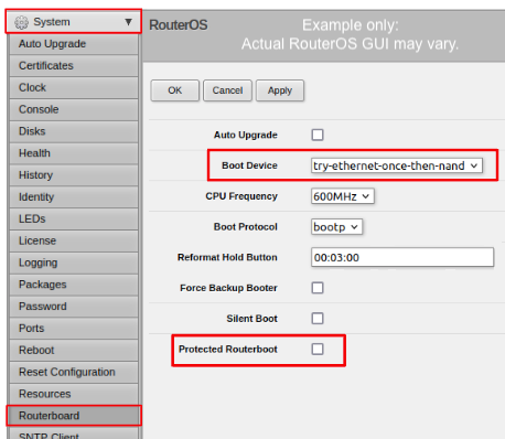
For Mikrotik devices you will use what is called Etherboot mode, and there are several ways to put your device into Etherboot mode (depending on the version of the manufacturer’s firmware it is running). The easiest way is to use the device’s reset button as described in the procedure below. If for some reason this does not work, then you can try logging into the Mikrotik RouterOS and setting System > Routerboard > Settings > Boot Device to try-ethernet-once-then-nand (either through the RouterOS web interface or via command line). Next time the device boots it will try Etherboot once before defaulting back to regular boot mode.
If your Mikrotik device has “Protected Routerboot” enabled, then you will need to disable it before proceeding. Use the manufacturer’s instructions to connect to your device and display the RouterOS web interface or command line. Navigate to System > Routerboard > Settings > Boot Device to uncheck or deselect Protected Routerboot. Click the Apply button, then you should be able to power down the device and continue with the steps in the AREDN® firmware install checklist.
Tip
There may be cases when your Mikrotik device boots the AREDN® kernel file but its RouterOS version does not allow the sysupgrade file to be installed. You can read the instructions on this page (OpenWRT - Procedures for RouterOS) to determine which version of Mikrotik RouterOS your device has. If it is running version 7.x then you can try installing the AREDN® sysupgrade v7 firmware file. Or you can downgrade Mikrotik RouterOS prior to flashing the regular AREDN® sysupgrade file. Earlier versions of RouterOS and their NetInstall utilities can be found on the Mikrotik website. Download an ARM version (routeros-arm) for devices that use the ipq40xx AREDN® firmware, or download a MIPSBE version (routeros-mipsbe) for other Mikrotik devices. Typically you can install a RouterOS version that is equal to or newer than the RouterOS version shown in the Factory Firmware field on the Mikrotik web display.
Mikrotik Install preparation#
Download both of the appropriate Mikrotik kernel and sysupgrade files from the AREDN® website. Rename the initramfs-kernel file to
rb.elfand keep the sysupgrade bin file available for later.Set your computer’s Ethernet network adapter to a static IP address on the subnet you will be using for the new device. This can be any network number of your choice, but it is recommended that you use the 192.168.1.x subnet. Using the 192.168.1.x network on your server will avoid having to change IP addresses on your computer during the install process. AREDN® firmware uses the 192.168.1.x network once it is loaded, so using it all the way through the process will simplify things for you. For example, you can give your computer a static IP such as 192.168.1.10 with a netmask of 255.255.255.0. You can choose any number for the fourth octet, as long as it is not within the range of DHCP addresses you will be providing as shown below.
Connect an Ethernet cable from your computer to the network switch as described at the top of this document, then connect another cable from the LAN port of the PoE adapter to the switch. Finally connect an Ethernet cable from the POE port to the node, but leave the device powered off for now. If you are flashing a device which uses a separate power adapter (such as a Mikrotik hAP ac family device), connect the last Ethernet cable from the switch to the device’s WAN port [1].
Boot the kernel image#
- Linux Procedure
If you are using a Linux or MacOS computer, use the following steps.
Create a directory on your computer called
/tftpand copy therb.elffile there.Determine your computer’s Ethernet interface name with
ifconfig. It will be the interface you set to 192.168.1.10 above. You will use this interface name in the command below as the name after-iand you must substitute your login user name after-ubelow. Use adhcp-rangeof IP addresses that are also on the same subnet as the computer: for example 192.168.1.100,192.168.1.200 as shown below.Open a terminal window to execute the following dnsmasq command with escalated privileges:
> sudo dnsmasq -i eth0 -u joe --log-dhcp --bootp-dynamic --dhcp-range=192.168.1.100,192.168.1.200 -d -p0 -K --dhcp-boot=rb.elf --enable-tftp --tftp-root=/tftp/
With the unit powered off, press and hold the reset button on the radio while powering on the device. Continue to hold the reset button until you see output information from the computer window where you ran the dnsmasq command, which should happen after 20-30 seconds. Release the reset button when you see the “sent” message, which indicates success, and you can now <ctrl>-C or end dnsmasq.
The node will now automatically reboot with the temporary AREDN® Administration image.
- Windows Procedure
If you are using a Windows computer, use the following steps.
Configure the PXE Server on your Windows computer. The example below uses Tiny PXE. For more information, see the Preparing Your Computer section above.
Navigate to the folder where you extracted the Tiny PXE software and edit the
config.inifile. Directly under the[dhcp]tag, add the following line:rfc951=1then save and close the file.Copy the
rb.elffile into thefilesfolder under the Tiny PXE server directory location.Start the Tiny PXE server exe and select your computer’s Ethernet IP address from the dropdown list called
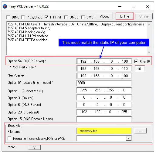
Option 54 [DHCP Server], making sure to check theBind IPcheckbox. Under the “Boot File” section, enterrb.elfinto the the Filename field, and uncheck the checkbox for “Filename if user-class = gPXE or iPXE”. Click the Online button at the top of the Tiny PXE window.

With the unit powered off, press and hold the reset button on the node while powering on the device. Continue holding the reset button until you see
TFTPd: DoReadFile: rb.elfin the Tiny PXE log window.Release the node’s reset button and wait for the image to be transferred to the device. You are finished using Tiny PXE when the firmware image has been read by the node, so you can click the Offline button in Tiny PXE.
The node will now automatically reboot with the temporary AREDN® Administration image.
Install the sysupgrade firmware image#
After booting the kernel image the node will have a default IP address of 192.168.1.1. Your computer should already have a static IP address on this subnet, but if not then give your computer an IP address on this subnet.
Important
For the Mikrotik hAP ac family of devices, disconnect the Ethernet cable from the WAN port (1) on the Mikrotik and insert it into one of the LAN ports (2,3,4) before you proceed.
You should be able to ping the node at 192.168.1.1. Don’t proceed until you can ping the node. You may need to disconnect and reconnect your computer’s network cable to ensure that your IP address has been reset. Also, you may need to clear your web browser’s cache in order to remove cached pages remaining from your node’s previous firmware version.
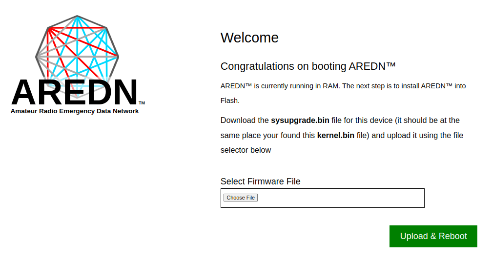
In a web browser, enter the URL
http://192.168.1.1to display the page for selecting the sysupgrade file. Browse to find the sysupgrade file you previously downloaded to your computer, select it, and click theUpload & Rebootbutton.
After successfully installing the sysupgrade file the node will automatically reboot to the new AREDN® firmware image.
TP-LINK first install process#
These devices may allow you to use the manufacturer’s native web interface to apply new firmware images. If available, this is the most user-friendly way to install AREDN® firmware. Navigate to the system setup menu to select and upload new firmware. Check the TP-LINK documentation for your device if you have questions about using their built-in user interface. If this process works then you will have AREDN® firmware installed on your device and you skip all of the steps described below.
If the process above does not work or if you choose not to use the PharOS web interface, then you can install AREDN® firmware on your device using steps similar to those described above for Mikrotik devices. TP-LINK devices are programmed to use TFTP for downloading a boot image from an external source. If you already have a PXE server on your Windows computer then you can use that. The example below uses Tiny PXE. It may also be possible to use a simple TFTP server instead. For more information, see the Preparing Your Computer section above.
- Install Preparation
Download the appropriate TP-LINK factory file and rename this file as
recovery.binSet your computer’s Ethernet network adapter to a static IP address of 192.168.0.100.
Connect an Ethernet cable from your computer to the network switch, and another cable from the LAN port of the PoE adapter to the switch. Finally connect an Ethernet cable from the POE port to the node, but leave the device powered off for now.
- Linux Procedure
Create a directory on your computer called
/tftpand copy the TP-LINKrecovery.binfile there.Determine your computer’s Ethernet interface name with
ifconfig. It will be the interface you set to 192.168.0.100 above. You will use this interface name in the command below as the name after-iand you must substitute your login user name after-ubelow. Use adhcp-rangeof IP addresses that are also on the same subnet as the computer: for example 192.168.0.110,192.168.0.120 as shown below.Open a terminal window to execute the following dnsmasq command with escalated privileges:
> sudo dnsmasq -i eth0 -u joe --log-dhcp --bootp-dynamic --dhcp-range=192.168.0.110,192.168.0.120 -d -p0 -K --dhcp-boot=recovery.bin --enable-tftp --tftp-root=/tftp/
With the unit powered off, press and hold the reset button on the radio while powering on the device. Continue to hold the reset button until you see output information from the computer window where you ran the dnsmasq command, which should happen after 20-30 seconds. Release the reset button when you see the “sent” message, which indicates success, and you can now <ctrl>-C or end dnsmasq.
The node will now automatically reboot with the new AREDN® firmware image.
- Windows Procedure
Configure the PXE or TFTP Server on your Windows computer. The example below uses Tiny PXE. For more information, see the Preparing Your Computer section above.
Navigate to the folder where you extracted the Tiny PXE software and edit the
config.inifile. Directly under the[dhcp]tag, add the following line:rfc951=1then save and close the file.Copy the
recovery.binfirmware image into thefilesfolder under the Tiny PXE server directory location.Start the Tiny PXE server exe and select your computer’s Ethernet IP address from the dropdown list called
Option 54 [DHCP Server], making sure to check theBind IPcheckbox. Under the “Boot File” section, enterrecovery.bininto the the Filename field, and uncheck the checkbox for “Filename if user-class = gPXE or iPXE”. Click the Online button at the top of the Tiny PXE window.
With the unit powered off, press and hold the reset button on the node while powering on the device. Continue holding the reset button until you see
TFTPd: DoReadFile: recovery.binin the Tiny PXE log window.Release the node’s reset button and wait for the image to be transferred to the device. You are finished using Tiny PXE when the firmware image has been read by the node, so you can click the Offline button in Tiny PXE.
The node will now automatically reboot with the new AREDN® firmware image.
GL-iNet first install process#
These devices allow you to use the manufacturer’s pre-installed OpenWRT web interface to upload and apply new firmware images. Check the GL-iNet documentation for your device if you have questions about initial configuration. GL-iNet devices provide DHCP services, so you should be able to connect your computer and automatically receive an IP address on the correct subnet. GL-iNet devices usually have a default IP address of 192.168.8.1, so if for some reason you need to give your computer a static IP address you can use that subnet.
After the GL-iNet device is first booted and configured, navigate to the Upgrade section and click Local Upgrade to select the AREDN® sysupgrade.bin file you previously downloaded to your computer.
Warning
Be sure to uncheck the Keep Settings checkbox, since GL.iNet settings are incompatible with AREDN® firmware. Also, the AR300M16 devices may have a boot_dev switch, so be sure to read the GL.iNet boot documentation to select the correct boot mode.
The node will automatically reboot with the new AREDN® firmware image. If for some reason you need to recover your device to factory firmware, you can search the GL-iNet website for a recovery procedure such as the process documented here: GL-iNet debrick procedure
Cudy first install process#
Cudy Travel Routers use a customized version of OpenWRT software, but the “Update Firmware” option in the Cudy web interface only accepts their RSA-signed images. At the present time Cudy provides a generic signed OpenWRT image so that customers can install another OpenWrt version of their choice. This situation adds an extra step to the normal OpenWRT upgrade process:
Login to the stock Cudy web interface and use the “Upgrade Firmware” option to install the intermediate firmware image provided by Cudy to OpenWRT (for example,
cudy_tr3000-v1-sysupgrade.bin)Login to the newly installed intermediate OpenWRT firmware and use “System > Flash Firmware” to install the appropriate AREDN® firmware image
Check the Cudy documentation for your specific device if you have questions. Several models of Cudy Travel Router are supported (for example: Cudy TR1200 v1 and Cudy TR3000 v1). Since these models use different chipsets, be sure to obtain the correct installation files for your specific model. The example below uses the TR3000 image.
Download the Cudy intermediate firmware image for your device and save it to your computer. At the present time there is a download link toward the bottom of this Cudy FAQ post. Be sure to download the correct intermediate firmware for your specific model. Unzip this file to extract the Cudy intermediate image as a
sysupgrade.binfile.Download the appropriate AREDN® firmware image for your specific device and save the AREDN®
sysupgrade.binfile to your computer.Power on the Cudy router and connect your computer to the LAN port of the Cudy using an Ethernet cable. Your computer should receive an IP address on the 192.168.10.x network from the Cudy DHCP server. Using a web browser, navigate to
http://192.168.10.1. Follow the initial step to create an admin password for the router, then clickExitto display the Cudy web interface.Navigate to General Settings and click the Firmware button in the left navigation bar. In the Local Update section, click the
Browsebutton and select the Cudy intermediate firmware image you previously downloaded from their download link. For example:cudy_tr3000-v1-squashfs-sysupgrade.bin. Click theProceedbutton to flash the Cudy intermediate firmware.After the device reboots, it will be running the intermediate “unlocked” version of OpenWRT using the stock IP network (192.168.1.x). Your computer will need to reconnect to the device in order to receive a new IP address from the OpenWRT DHCP service. You may now navigate to
http://192.168.1.1and login using the root username without a password.In the OpenWRT web interface, navigate to System > Backup/Flash Firmware. In the Flash Firmware Image section click the
Flash Imagebutton. Browse to select the AREDN® firmware you previously downloaded for your specific device, then click theUploadbutton.
Warning
In the “Flash image?” box, be sure you deselect/uncheck the box for “Keep settings and retain the current configuration.” Existing Cudy/OpenWRT settings are not compatible with the AREDN® firmware.
The node will automatically reboot after installing AREDN®, and you may need to refresh your computer’s network interface to receive a new IP address before continuing to the Firstboot node setup steps in the Getting Started section.
If for some reason you need to recover your device to factory firmware, you can search the Cudy website for a recovery procedure such as the process documented here: Cudy recovery procedure. You connect your computer to the WAN port of the Cudy, and the Cudy original firmware must be renamed to recovery.bin.
OpenWRT One first install process#
These devices allow you to use the manufacturer’s pre-installed OpenWRT web interface to upload and apply new firmware images. Check the OpenWRT One documentation if you have questions. This device provides DHCP services, so you should be able to connect your computer to its LAN port to automatically receive an IP address on the correct subnet. OpenWRT One devices have a default IP address of 192.168.1.1, so if for some reason you need to give your computer a static IP address you can use the 192.168.1.x/24 subnet.
Important
OpenWRT One devices have a boot mode switch. Be sure the boot mode is set to NAND (the normal operational setting) before following the example flashing procedure below.
There are several methods for upgrading OpenWRT. The OpenWRT One device also provides a USB upgrade method. The example procedure below uses the OpenWRT web interface (LuCi GUI).
Cable your computer’s Ethernet port to the router’s LAN port, which is the
1GEthernet port next to the Reset button. Power on the OpenWRT One and verify that your computer received an IP address from the device’s DHCP service. Verify that you can ping the device at 192.168.1.1.Open a web browser and navigate to
http://192.168.1.1. On a fresh device you can login using the default root username with an empty password field. If you have already changed the root password, then login using your own password.Navigate to
System>Backup/Flash FirmwareGo to the
Flash new firmware imagesection and click theFlash imagebuttonClick
Choose Fileto select the AREDN® sysupgrade.bin file you previously downloaded to your computer, then click theUploadbutton to upload the new imageUNCHECK the
Keep settingscheckbox, then clickContinueto flash the AREDN® firmware
The node will automatically reboot after installing AREDN®, and you may need to refresh your computer’s network interface to receive a new IP address before continuing to the Firstboot node setup steps in the Getting Started section.
MorseMicro device install process#
Supported models currently include HaLowLink 1, Heltec HT-HD01 & HT-HD7608, and Alfa Tube-AHM. These devices allow you to use the manufacturer’s pre-installed OpenWRT web interface to upload and apply new firmware images. This device provides DHCP services, so you should be able to connect your computer to its LAN port to automatically receive an IP address on the correct subnet.
Cable your computer’s Ethernet port to the radio’s LAN port. Power on the MorseMicro device and verify that your computer received an IP address from the device’s DHCP service.
Open a web browser and navigate to
http://192.168.x.1wherexis the subnet on which your computer IP address was provided. On a fresh device you can login using the default username and password shown in your device’s instructions. If you have already changed the password, then login using your own password.Navigate to
System>Backup/Flash Firmwareand go toFlash new firmware imageUNCHECK the
Keep settingscheckboxClick
Choose Fileto select the AREDN® sysupgrade.bin file you previously downloaded to your computerClick
Flash imageto upload the AREDN® firmware
The node will automatically reboot after installing AREDN®, and you may need to refresh your computer’s network interface to receive a new IP address before continuing to the Firstboot node setup steps in the Getting Started section.
Zyxel device install process#
The Zyxel NWA55AXE allows you to use the manufacturer’s native web interface to apply new firmware images. Follow the guidelines in the Zyxel User Guide for connecting the device to the supplied PoE to power it on. Use an Ethernet cable to connect the Zyxel LAN port to your Ethernet switch where your computer is also connected (see diagram at the top of this section).
Check the Zyxel User Guide for the steps for accessing the web configurator. By default the Zyxel device has an IP address of 192.168.1.2, so give your computer an IP address in the 192.168.1.x subnet (for example, 192.168.1.10). Open your web browser and navigate to http://192.168.1.2 where you will be prompted to enter a username and password. By default the Zyxel admin account uses the password that is printed on the label attached to the device. Select your preferred language and choose the Standalone management mode.
In the navigation bar on the left, click the Configuration icon and navigate to the Maintenance menu. Under File Manager select Firmware Package. To upload the AREDN® firmware, browse to the appropriate FACTORY image you previously downloaded from the AREDN® Firmware Selector, then click the Upload button. The node will automatically reboot with an IP address of 192.168.1.1 so that you can configure the AREDN® firmware.
The OpenWRT information page for this device may provide additional help for more in-depth troubleshooting.
After the AREDN® firmware install#
After the node reboots, it should have a default IP address of 192.168.1.1. Make sure your computer has an IP address on the 192.168.1.x network. You should be able to ping the node at 192.168.1.1. Don’t proceed until you can ping the node. You may need to disconnect and reconnect your computer’s network cable to ensure that it has a connection.
Once your device is running AREDN® firmware, you can display its web interface by navigating to either http://192.168.1.1 or http://localnode.local.mesh. Some computers may have DNS search paths configured that require you to use the fully qualified domain name (FQDN) to resolve localnode to the mesh node’s IP address. You may need to clear your web browser’s cache in order to remove any cached pages.
You can use your web browser to configure the new node with your callsign, admin password, and other settings as described in the Firstboot Node Setup section of the documentation.